Description
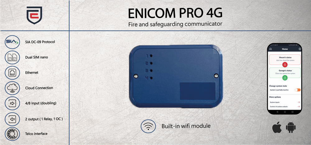
EniCom 4G Pro communicators are recommended for security and fire protection applications, where the signal transmission to the monitoring station must be solved by providing a redundant transmission path. The primary reporting path is the Ethernet network; a mobile network (GPRS, LTE ) or Wi-Fi network (optional) can be used as the secondary path. Standard IP-based protocols do the reporting.
In most cases, the EniCom 4G Pro communicator must be connected to the line connection of the alarm centre (TIP/RING). The built-in telephone interface simulates the telephone line; through this, the communicator can receive signals from the alarm centre. The communicator then automatically receives the signals via the telephone line connection of the alarm centre and forwards them to the supervisor via the set communication channels. In the configuration, you can set how the communicator acknowledges the received events to the alarm centre. By default, it acknowledges immediately, but only if the "Passthrough" option is used if the event has already been successfully submitted on one of the routes. This allows for slower, but in many cases, more secure transfers.
The EniCom 4G Pro communicator can also receive contact signals from the centre on its input and then transmit them to the monitoring station via the Ethernet / WIFI / Mobile (LTE) network.
EniCom 4G Pro communicators can send messages to monitoring station receiver(s) via Ethernet, WI-FI or mobile internet network. Four independent communication paths can be defined, each with 4 communication channels (Ethernet, WI-FI and Modem: 2pcs GSM/4G networks, thanks to the 2 SIM cars), to which four arbitrary servers can be assigned on different media (Ethernet or GPRS/LTE).

Among the report modes, you can choose from 4 predefined settings:
- 1 Path (channel)
- 1 Path (server)
- Channel paths
- Server paths
DHCP is the default setting for connecting to an Ethernet network; network properties are assigned automatically. Of course, the function can be turned off, and the network parameters can be entered manually.
The communicator can manage two SIM cards, so if the primary service provider is unavailable, it can also connect to the network of the secondary service provider.
The EniCom 4G Pro has a WiFi/WLAN interface. The wireless LAN can also be used for connecting to the network.
The EniCom 4G Pro communicator is usually connected by the telco interface (TIP and RING terminals) to the security control panel. The communicator receives the reports over its telco interface and forwards the messages to the AMS servers.
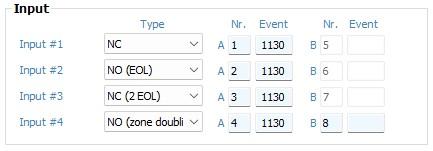
The loop type of the inputs can be programmed as NC or NO, without or with 1 or 2 EOL resistors, or can be doubled using 3 EOL resistors. The standard value for EOL resistors is 1kΩ. In case of zone doubling, the 3rd EOL resistor should be 2kΩ. EC-84 expansion module selectable input types NO/NC EOL.

The communicator has two OC outputs, which can be freely configured as NO / NC and bistable or monostable:

EniCom 4G Pro communicators can establish a connection with the cloud service. This is completely independent of the specific application and the reporting routes set up. Remote control and remote programming of devices are possible through the cloud connection.
- Instant two-way transfer (Contact ID)
- Plastic housing, SMA antenna connector
- Automatic configuration of network settings (DHCP)
- Send to four remote monitoring stations via Ethernet/WIFI
- Send to four remote monitoring stations on GPRS/HSPA/UMTS
- Backup / Parallel / GPRS/HSPA/UMTS/Ethernet/WIFI transmission modes
- Remote programmability
- SMS forwarding to 1 specified phone number
- 256 event buffer memory
- Encryptable communication
- Configuration via USB and Cloud
- The main functions can be programmed with SMS messages
- Four own inputs that can be doubled with adjustable event codes
- can be expanded with EC-IO84 panel with 8 inputs and 4 outputs (optional) max. 8 can be connected (64/32 inputs/outputs in total)
- Upgradeable firmware
- EN 54-21 compliance

Parameters
| Power Supply | 10 – 28,0 V DC |
| Standby Current | 150 mA (average) |
| Maximal Current | 1000 mA (peak) |
| Inputs / Outputs | 4 / 2, expandable with the EC-84 |
| Output type/rating | Open collector @ max. 50 mA, relay @ max. 1A (optional) |
| Ethernet connection | 10/100 Base T (RJ 45) |
| Antenna | SMA |
| USB connection | USB 2.0 CDC/MSD |
| Event Buffer | 512 events, with timestamp |
| Operating conditions | 0 °C...50 °C , rel.60% |
| Size (W / L / H) | 135 x 95 x 25 mm |
| Weight | 140 g |


